
A Cooler Cold Plate is a compact heat-transfer component designed to remove heat from electronics, batteries, lasers, processors, and other high-power devices. It usually contains internal channels, a metal body, and a circulating coolant. Heat travels from the device into the plate, then moves into the fluid. The warmed fluid leaves, and cooler fluid returns. Simple in principle. Demanding in practice.
Dr. Avram Bar-Cohen, a recognized thermal-management researcher, has stated, “Heat must be managed where it is generated.” This idea explains the value of a Cooler Cold Plate. Placing the cooling path directly beneath a power module reduces thermal resistance and helps limit dangerous temperature peaks. Copper spreads heat quickly. Aluminum reduces weight. Channel shape controls pressure drop, turbulence, and coolant contact.
Still, the cold plate is not automatically efficient. A poorly machined channel can create uneven cooling. A weak seal can cause leakage. Excessive pump pressure can increase energy use without improving performance. These details matter. Real installations are messier than diagrams suggest.
This article examines what a Cooler Cold Plate is, how it works, and why engineers select different materials and channel designs. It also considers mounting pressure, thermal interface materials, flow distribution, corrosion control, and service life. Readers will see how heat moves through the complete assembly, from the device surface to the coolant loop. The discussion remains practical, but one limitation deserves attention: laboratory results may not match field conditions. Dust, vibration, aging seals, and changing workloads can alter performance. A reliable design must expect those imperfections.
A cooler cold plate is a reusable thermal insert designed to absorb heat inside an insulated cooler. Its purpose is to help maintain a controlled holding range, often between 2°C and 8°C. This range is widely used for temperature-sensitive materials, but performance depends on the cooler, load size, opening frequency, and outside temperature.
The cold plate usually has a sealed outer shell filled with a phase-change material. After conditioning in a freezer or temperature-controlled unit, the material stores cooling energy. Inside the cooler, it absorbs incoming heat while gradually changing state. This process is more stable than ordinary loose ice because it reduces direct contact with stored items and limits water buildup. The plate needs the right conditioning time. Too little time may leave its center warm.
In practical use, place the plate according to the cooler’s airflow and load layout. Avoid pressing sensitive contents directly against a frozen surface. A small gap or protective layer can prevent local freezing. Use a calibrated thermometer or data logger to verify the actual temperature. The 2–8°C range is not automatic. A crowded cooler may hold heat longer, while an opened lid can quickly disturb the balance. Even careful testing can miss weak points, especially during transport. That is why repeated checks under realistic conditions remain important.
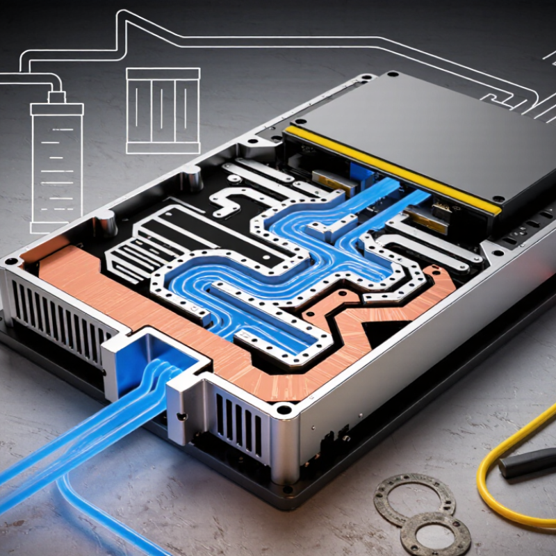
A cooler cold plate is a machined metal block that moves heat from electronics into a liquid coolant. Channels inside the plate carry water or another engineered fluid. The coolant absorbs heat and transports it to a remote heat exchanger.
Material choice strongly affects the design. At about 20°C, aluminum conducts roughly 205 W/m·K, while copper reaches nearly 400 W/m·K.
These figures align with values published in the Aluminum Association’s Aluminum Standards and Data and the Copper Development Association’s technical handbook.
Copper can therefore spread heat faster across a compact plate. It is also much denser, which increases system weight.
Aluminum offers easier handling and often simpler manufacturing. Its lower conductivity may require thicker walls or more carefully positioned channels.
The comparison is useful, but incomplete. Thermal resistance also depends on channel geometry, coolant flow, surface flatness, and contact pressure.
ASHRAE’s Thermal Guidelines for Data Processing Environments emphasizes the importance of complete cooling-system design, not material conductivity alone.
In practical testing, a copper plate may outperform aluminum near a concentrated processor hotspot. Aluminum can remain effective when the heat load is distributed across a larger area.
Corrosion control matters too, especially when dissimilar metals share a loop.
A small design compromise can become a measurable temperature rise.
A cooler cold plate uses a phase change material (PCM) to store cooling energy. The PCM is selected to melt and freeze within a controlled temperature range. Refrigerant flows through an evaporator channel connected to the plate. As the refrigerant evaporates, it absorbs heat from the PCM and lowers its temperature.
The PCM then freezes. This process stores energy as a solid phase, rather than simply reducing the plate’s temperature. During later cooling demand, the frozen PCM slowly melts and absorbs heat from nearby products or equipment. The plate can remain close to its phase-change temperature for a useful period. That stability helps protect temperature-sensitive contents during short power interruptions or peak-load conditions.
A practical system needs good thermal contact. Poor contact creates cold and warm zones. The refrigerant circuit also needs accurate pressure control, because excessive cooling may freeze the wrong components or waste energy. Sensors can track plate temperature, refrigerant behavior, and charging time. The design is not flawless. A thicker PCM layer may store more latent energy, yet it can freeze slowly. In real testing, airflow, insulation, and repeated cycles often affect performance more than calculations suggest. Small gaps matter. A reliable cold plate therefore combines measured data, suitable PCM selection, and careful mechanical design.
A cooler cold plate transfers heat from a warm object into a circulating coolant. Conduction begins at the contact surface. Heat moves through the plate’s solid material, following the temperature gradient. Copper conducts approximately 398 W/m·K at room temperature, while aluminum reaches about 237 W/m·K, according to reference data from the National Institute of Standards and Technology. These values explain why engineers often select metals with low thermal resistance. Flatness matters too. A tiny air gap can interrupt the thermal path.
The coolant removes heat through convection inside channels, tubes, or drilled passages. Water conducts about 0.6 W/m·K, but moving water can carry substantial heat because its specific heat is high. Air is much less effective, with thermal conductivity near 0.026 W/m·K, as reported in thermophysical property references. ASHRAE’s Handbook—Fundamentals explains that convection depends on fluid velocity, surface area, and the temperature difference between the wall and fluid. Faster flow usually improves heat transfer, but pressure loss also increases.
In practice, technicians inspect contact marks, flow balance, and outlet temperature. A cooler outlet is not automatically proof of better performance. The cold plate may still contain hot spots. I have found that simplified calculations often look convincing, yet real assemblies behave differently. Manufacturing tolerances, pump limits, and uneven mounting can alter results. That is why engineers compare thermal-resistance estimates with measured temperatures under stable loads.
A cold plate transfers heat from a warm component to a coolant. Heat moves through the solid plate mainly by conduction, then leaves the plate through convection into the moving coolant.
How to read the chart: Materials with higher thermal conductivity transfer heat more easily. Copper and aluminum are effective cold-plate materials, while the coolant removes heat from the plate by convection. Values are representative thermal conductivity figures near room temperature.
A cooler cold plate stores cooling energy inside a dense metal surface. Refrigerant or another cooling medium removes heat from the plate. When warm products touch it, heat moves into the plate through conduction. The system then restores the lost cooling energy during the next cycle. Simple in theory.
Capacity describes how much heat the plate can absorb before its temperature rises too far. It depends on plate mass, operating temperature, surface contact, insulation, and product load. A larger capacity may support heavier loads, but it can also require more recovery time. Capacity alone does not define performance.
Pull-down time measures how quickly the cooler reaches its target temperature. Testing should record temperatures at several product locations, not only near the plate. ASHRAE 72 testing provides controlled conditions for evaluating refrigerators and freezers. It can examine temperature performance, energy use, and recovery behavior under repeatable procedures. Results become more useful when technicians document ambient temperature, product mass, starting temperature, and sensor placement. Small setup differences matter.
A cold plate may pass a short test yet struggle during repeated door openings. That is where real operation becomes less predictable. The test is valuable, but it is not a perfect copy of every workplace. Engineers should compare rated capacity with actual demand and review pull-down curves, not only final temperature. Mistakes happen when one impressive number carries too much weight.
Contact Us