Blog

You are here:

How to Choose the Right Electric Gate Valve?

Choosing the right Electric Gate Valve begins with understanding the pipeline, not the product catalog. The valve must match the fluid, pressure, temperature, pipe size, and operating frequency. Water service differs greatly from steam, chemicals, or abrasive slurries. Small details matter.

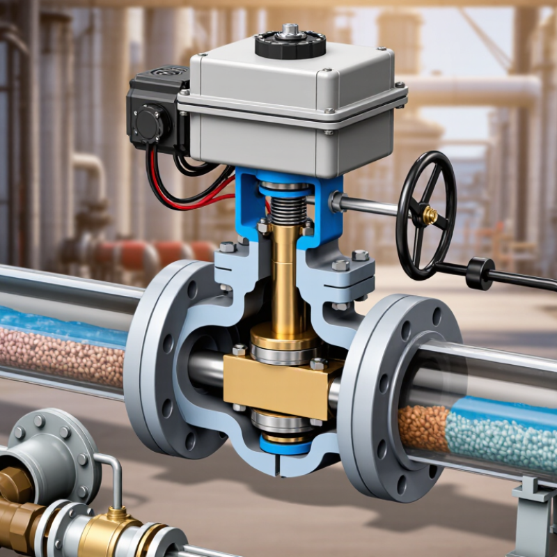
In field applications, valve failures often begin with an overlooked actuator requirement. Check torque output, power supply, enclosure protection, travel time, and manual override access. A dusty outdoor installation may need a higher IP rating. A corrosive process may require stainless steel or specially lined components. The valve body, seat, stem, and actuator should be reviewed as one system. Do not select by diameter alone. That shortcut can become expensive.

Gate valves are generally designed for full open or full closed service. They are usually not suitable for continuous throttling. Confirm this point with the manufacturer and the responsible engineer. Reliable selection also requires verified drawings, performance curves, material certificates, and applicable industry standards. Independent inspection can strengthen confidence when the application is critical. Yet paperwork does not replace practical judgment. I have seen technically compliant valves perform poorly because installation space was ignored. Maintenance access matters. So does actuator position.

A sound decision balances service conditions, lifecycle cost, availability, and future maintenance. Compare more than purchase price. Ask how quickly replacement parts can arrive and whether local technicians understand the actuator. The ideal Electric Gate Valve is not simply powerful. It is correctly matched, clearly documented, and realistic for the people who will operate it. Mistakes remain possible, but careful verification makes them less likely.

How to Choose the Right Electric Gate Valve?

Understand the Purpose and Operating Conditions of the Electric Gate Valve

Choosing the right electric gate valve starts with its purpose and operating conditions. A gate valve is designed for full isolation, not routine throttling. Partial opening can cause vibration, seat damage, and unstable flow. The U.S. Department of Energy’s Improving Pumping System Performance sourcebook estimates that pumping systems may consume 20–25% of industrial electricity. A poorly selected valve can increase this hidden load.

Define the medium first. Record pressure, temperature, pipe size, flow direction, and the fluid’s solids content. Then check the required shutoff pressure and operating frequency. Electric actuator torque must exceed the valve’s breakaway torque, especially after long periods without movement. Consider power failure behavior, enclosure protection, manual override, and available voltage. ISO 5210 and IEC 60529 provide useful references for actuator interfaces and ingress protection. Field conditions matter more than a neat catalogue table.

Tips: Ask whether the valve will isolate or regulate. Confirm the real closing time. Check torque at the coldest expected temperature. Leave a reasonable safety margin, but avoid excessive sizing. An oversized actuator may cost more and cycle poorly. I have seen selections fail because engineers trusted normal pressure instead of startup pressure. That mistake is easy to repeat. Review the worst operating case with maintenance staff before ordering.

Select the Correct Valve Size, Pressure Rating, and Connection Type

How to Choose the Right Electric Gate Valve?

Correct valve selection starts with size, not the actuator. Match the valve bore to the required flow rate, pipe velocity, and allowable pressure loss. A larger valve is not automatically safer. Oversizing can reduce flushing velocity and leave the gate operating inefficiently. Use the manufacturer’s flow coefficient data, then verify the result against AWWA Manual M49 guidance for water-system control. Field measurements matter. Old drawings can be wrong.

Pressure rating must cover normal pressure, temperature effects, and water hammer. ASME B16.34 requires pressure-temperature limits to be considered, while ISO 5208 provides leakage-testing classifications. Do not select a valve rated only for average pressure. Include pump-startup spikes and emergency closure conditions. The U.S. Department of Energy reports that motor-driven systems consume more than 70% of industrial electricity, so actuator efficiency and duty cycle deserve attention. The valve may be small, but its operating energy is not always small.

Connection type must match the pipeline standard and installation space. Flanged ends suit frequent maintenance, while threaded connections fit smaller, lower-pressure lines. Wafer and lug designs need careful checking for bolt length and flange alignment. Confirm face-to-face dimensions using ISO 5752 or the project specification. Calculate actuator torque from seating, unseating, packing friction, and line pressure. Add a practical safety margin, but avoid excessive sizing. More torque is not always better. It can damage the stem.

How to Choose the Right Electric Gate Valve? — Select the Correct Valve Size, Pressure Rating, and Connection Type
Selection Dimension Typical Options Recommended Selection Guidance Important Technical Checks
Nominal Valve Size DN15 to DN300 and larger
(approximately NPS 1/2 to NPS 12)
Select a valve with a nominal bore that matches the connected pipe size. For most full-port gate valves, the flow passage is intended to provide low resistance when fully open. Confirm the nominal size standard used by the piping system, such as DN under ISO/EN practice or NPS under ASME practice. Do not select a valve based only on the outside diameter of the pipe.
Small-Bore Service DN15–DN50
(NPS 1/2–NPS 2)
Threaded or socket-welded connections are commonly used where the line is compact and installation space is limited. Flanged versions are also available for easier maintenance. Check thread form, thread direction, pipe schedule, sealant compatibility, and the available space for the electric actuator.
Medium-Bore Service DN65–DN200
(NPS 2 1/2–NPS 8)
Flanged valves are often preferred for water, HVAC, utility, and general industrial piping because they allow removal without cutting the pipe. Verify flange outside diameter, bolt-hole pattern, bolt size, gasket type, and face-to-face dimension against the piping standard.
Large-Bore Service DN250 and above
(NPS 10 and above)
Use a valve designed for the pipeline's operating conditions. Larger valves require particular attention to actuator torque, stem load, mounting orientation, and structural support. Confirm lifting provisions, actuator output torque, emergency manual override, installation clearance, and the maximum allowable stem thrust.
Pressure Rating: ASME Class Class 150, 300, 600, 900 and higher Choose a pressure class equal to or higher than the maximum design pressure and temperature combination of the piping system. ASME Class ratings are pressure-temperature ratings, not a single pressure value. The allowable pressure changes with valve body material, trim material, and operating temperature. Check the applicable pressure-temperature table.
Pressure Rating: EN PN PN10, PN16, PN25, PN40 and higher PN16 is commonly used in many water and utility systems, while higher PN ratings may be required for higher-pressure services. PN designations must match the flange drilling and the valve's certified pressure-temperature limits. PN16 and ASME Class 150 are not automatically dimensionally interchangeable.
Operating Pressure Normal pressure, maximum working pressure, and design pressure Base the selection on the maximum design pressure, not only the normal operating pressure. Include possible pump shutoff pressure and pressure surges. Consider water hammer, rapid pump starts or stops, trapped pressure, and pressure relief arrangements. The actuator must also be suitable for the differential pressure across the gate.
Temperature Range Ambient, cold water, hot water, steam, or process temperature Select body, seat, stem packing, gasket, and actuator materials for the complete minimum and maximum temperature range. Pressure capacity generally decreases as temperature rises. Check elastomer limits, insulation requirements, actuator temperature limits, and condensation protection.
Connection Type: Flanged Raised face, flat face, or ring-type face depending on the system Select flanged valves when reliable disassembly, inspection, and replacement are important. Common dimensional references include ASME B16.5, ASME B16.47, EN 1092-1, and EN 558. Match flange standard, pressure class or PN rating, facing type, bolt-hole arrangement, gasket material, and face-to-face length.
Connection Type: Threaded Female NPT, BSPP, or BSPT, depending on the piping system Suitable mainly for smaller pipe sizes and services where frequent removal is not required. Use the same thread standard on the valve and the pipe or fitting. NPT, BSPP, and BSPT threads have different profiles and sealing methods. They should not be treated as automatically interchangeable. Confirm pressure limits and installation orientation.
Connection Type: Butt-Weld Weld ends sized for the pipe wall thickness Suitable for high-integrity systems where a permanent, compact, low-leakage connection is required. Match outside diameter and wall thickness. Follow the approved welding procedure, verify material weldability, and protect the valve seat and actuator from welding heat.
Connection Type: Socket-Weld Primarily used on small-bore piping Provides a compact permanent connection for compatible piping systems and higher-pressure small-bore applications. Confirm socket dimensions, pipe insertion requirements, welding clearance, and the applicable piping and welding standard.
Valve Body Material Ductile iron, carbon steel, stainless steel, or other specified alloys Select the body material according to pressure, temperature, fluid chemistry, corrosion risk, and mechanical requirements. Check corrosion resistance, chloride exposure, low-temperature toughness, compatibility with the fluid, and any applicable material certificates.
Gate and Seat Arrangement Wedge gate, resilient-seated gate, or metal-seated gate Resilient-seated designs are commonly used for clean water and utility isolation. Metal-seated designs may be preferred for higher temperatures, abrasive service, or demanding industrial applications. Gate valves are generally intended for fully open or fully closed isolation, not continuous throttling. Confirm leakage class, seat material, and fluid cleanliness.
Actuator Output Torque Torque sized for breakaway, running, seating, and unseating conditions Choose an electric actuator with sufficient torque and thrust for the valve at the maximum differential pressure and worst-case operating condition. Do not size the actuator from valve size alone. Include packing friction, seat friction, pressure effects, safety margin, duty cycle, and the valve manufacturer's torque/thrust data.
Actuator Control Mode On/off, modulating, local control, or remote control Use on/off control for isolation duties. Use a properly rated modulating actuator only when the system requires controlled positioning and the valve is suitable for that duty. Confirm control signal, feedback requirements, position indication, fail position, interlocks, and compatibility with the control system.
Electrical Supply Single-phase or three-phase AC; low-voltage DC where specified Select an actuator that matches the available voltage, frequency, phase, and starting-current capacity. Verify motor protection, overload protection, enclosure rating, cable entry, grounding, ambient temperature, and hazardous-area certification where required.
Installation Position Vertical stem, horizontal stem, or manufacturer-approved orientation Install the valve in the orientation recommended for the specific design, preferably with adequate clearance for actuator removal and manual operation. Avoid placing the actuator where it can be flooded, exposed to excessive heat, or obstructed by adjacent equipment. Confirm stem orientation and maintenance access.
Applicable Standards ASME B16.10, ASME B16.34, ASME B16.5, EN 1074, EN 1171, EN 558, ISO 5210, or project-specific standards Select standards based on the industry, country, piping code, and service category. Confirm that valve design, testing, face-to-face dimensions, flange dimensions, actuator mounting, and pressure testing requirements are covered by the selected standards.
Final Ordering Information Size, rating, connection, material, seat, actuator, power, control, and accessories Prepare a complete valve specification before purchase to prevent mismatched components and installation delays. Always verify the final selection against the system design pressure, temperature, fluid, applicable codes, certified product data, and the valve manufacturer's sizing information.

Compare Materials for Media Compatibility and Environmental Resistance

How to Choose the Right Electric Gate Valve?

Material choice begins with the media, not the valve price. Carbon steel suits many non-corrosive water and oil services. However, dissolved oxygen, chlorides, and acidic fluids can accelerate attack. Stainless steel offers stronger corrosion resistance, but grades differ significantly. Seawater can still damage unsuitable stainless alloys.

The NACE IMPACT study estimated global corrosion costs at about $2.5 trillion annually, equal to 3.4% of global GDP. That figure shows why environmental resistance deserves careful attention. For abrasive slurries, hardened internal parts may outperform standard stainless steel. For chemical service, verify concentration, temperature, and exposure time. A material chart helps, but it is not enough.

Temperature matters too. Thermal cycling can weaken seals and increase operating torque. Outdoor installations need weather-resistant enclosures, suitable ingress protection, and protection from ultraviolet exposure. API and ISO valve standards provide useful design guidance, but site conditions remain decisive. That assumption is often wrong.

Tips: Request compatibility data from the valve manufacturer and the fluid supplier. Check chloride levels, pressure, temperature, and cleaning chemicals. Inspect sample valves after service when possible. A short field test may reveal pitting that a catalogue misses. Also, do not select stainless steel automatically. It can be expensive, yet still unsuitable.

How to Choose the Right Electric Gate Valve?

Compare valve body materials by their general compatibility with common media and resistance to outdoor environmental exposure. Ratings use a practical 1–5 engineering index, where 1 is low and 5 is high. Actual selection must also consider concentration, temperature, pressure, lining, trim, and applicable standards.

Carbon steel and ductile iron are commonly used for water and general service but require protective coatings in corrosive environments. 316 stainless steel provides strong general corrosion resistance, although chloride-rich conditions can still cause pitting. PVC-U performs well with many dilute acids, salts, and water-based media, but its temperature and hydrocarbon limits are lower than metal materials.

Evaluate Actuator Features, Controls, and Power Requirements

Choosing an electric gate valve starts with the actuator, not the pipe size. Confirm breakaway, running, and seating torque from tested valve data. Add a practical safety margin, but avoid excessive oversizing. Large actuators can increase inrush current, cost, and closing stress.

Control mode matters in the field. On-off service needs clear open and close signals, limit switches, and position feedback. Modulating service requires proportional control, stable travel resolution, and a properly shielded signal cable. A 4–20 mA feedback loop helps operators detect partial travel. The U.S. Department of Energy reports that motor-driven systems consume more than half of industrial electricity use, so standby power and duty cycle deserve attention. Small details matter. Check enclosure protection under IEC 60529, especially where washdown or outdoor moisture is expected.

Match the actuator to available power, including voltage, phase, frequency, and starting current. A 24 VDC actuator may suit remote equipment, but long cables can create voltage drop. A 230 VAC model may simplify power delivery, yet it needs suitable isolation and local protection. IEC 60034-30-1 efficiency classes provide a useful motor-efficiency reference, although valve actuators are not ordinary continuous-duty motors. That comparison is imperfect. Specify rated duty, ambient temperature, manual override, thermal protection, and emergency operation separately. In practice, many failures begin with a control cabinet that was never checked against actuator inrush current.

Verify Installation, Maintenance, Safety, and Long-Term Performance

Choosing the right electric gate valve begins with the installation site, not the catalog. Measure pipeline size, pressure, temperature, flow direction, and available voltage. Confirm the actuator’s torque exceeds the valve’s breakaway torque. Leave practical space for handwheel access and actuator removal. The U.S. Department of Energy reports that motor-driven systems consume more than half of industrial electricity. Efficient actuator sizing therefore affects operating cost, not just purchase price.

Installation accuracy protects long-term performance. Keep the valve body aligned with the pipe, and prevent actuator weight from stressing the stem. Set open and closed limit switches after full manual travel. Test local and remote controls separately. Check enclosure protection against dust, moisture, and washdown conditions. ISO 55001 principles support recording asset condition, inspection results, and failure history. Small records matter.

Maintenance must be visible and repeatable. Inspect stem movement, terminal connections, seals, mounting bolts, and unusual noise. Lubricate only where the manufacturer’s instructions permit it. Test emergency isolation and lockout procedures before real demand occurs. The IEA’s Energy Efficiency 2023 report states that industry used about 37% of global final energy in 2022, making avoidable valve cycling worth investigating. In practice, teams sometimes check the actuator but ignore upstream pressure changes. That is an imperfect habit. A quarterly review of cycle counts, leakage, response time, and energy use can expose it. Safety should never depend on a single limit switch or an assumed fail position.

Article Source:

Go to Top